MultiWriter technology is available on CheckSum Analyst low cost in-circuit testers or in the standalone MultiWriter pps™ On-board Gang Programming System.
MultiWriter Part Programming Families
MultiWriter has a comprehensive library of supported parts families, which is being updated and expanded on an ongoing basis. The figure below shows the part manufacturers with currently supported devices in the Library. You can download an up-to-date list of supported parts by manufacturer.
Please contact CheckSum to inquire if the parts family you need is planned or currently in development.
Part Programming
The throughput of simultaneous programming with the flexibility of custom programming. MultiWriter allows unique data such as a date code or serial number for the parts to be programmed with minimal impact on programming time. The part serial number or other data such as an assembly serial number entered via bar code can be stored in a file or provided at run-time. Calibration or other measurement data can be programmed into each part separately as illustrated in the diagram below.
Smart ISP™
MultiWriter’s Smart ISP (In-System Programming) technology ensures that the ISP programming phase follows a defect-free in-circuit test of the board. The test system programs only boards that have passed the in-circuit tests. Only assemblies that have passed the opens/shorts and other component tests are powered-on. For example, if a panel has seven tested-good assemblies out of eight total, then only those seven will be powered-on for ISP device programming.
Using the Data Encryption Protection option insures your IP (Intellectual Property) is not at risk anywhere in the world. Unique data (e.g. serial number, date code, MAC address, calibration data, etc) can be written to individual chips, as they are being gang-programmed.
Board Design Considerations
As is the case in most designs, the circuit design must allow in-system programming such that the device can be programmed without the requirement to overdrive other signals. The ISP device programming pins must be accessible via a bed-of-nails fixture—just like any other in-circuit test point.
The board or multi-board panel assembly layout should provide electrical access to the programming pins that are as physically close as possible to the device being programmed in order to minimize crosstalk and noise.
Device Programming Considerations
MultiWriter allows unique data such as a date code or serial number for the parts to be programmed with minimal impact on programming time. The part serial number or other data such as an assembly serial number entered via bar code can be stored in a file or provided at run-time. Calibration or other measurement data can be programmed into each part separately. Since unique data is typically a very small portion of the overall part memory, the programming time for chip-unique data will be minimal. A standard data file format (INTEL hex, Motorola S-Record, SVF, STAPL) is used for storage of unique data that is accessed during the ISP programming process.
The MultiWriter Controller board has two operating modes: Program and Verify. In Program mode, the controller places the ISP chip in the “program” state and code appropriate to the device is retrieved from the computer memory and applied via the fixture-based buffer boards. Once chip programming is complete, the MultiWriter controller places the chip in the “read” state and the code just programmed is verified. The Program and Verify operations can occur on a Test Step basis.
The board assembly (or individual panel in a multi-up assembly) will be powered-up to program the part, so some test system power source must be available and sufficient.
* Up to 16 MultiWriter control modules with up to 24 buffer modules each for 384 maximum devices. One MultiWriter control module required for each different device type.
† MultiWriter Technology is protected under U.S. Patent No. 7,802,021.
MultiWriter On-Board Gang Part Programming
Programming CPLD (Complex Programmable Logic Device) parts such as microcontrollers, serial Flash and FPGAs after they are attached to the circuit board [’on-board programming’] simplifies the manufacturing process and reduces inventory and rework costs compared to mounting pre-programmed chips.
Since the contents of Phase Change Memory (also known as PCM, PCME, PRAM, PCRAM, and C-RAM) can be lost because of the high temperatures needed to solder the device to a board, on-board programming is required.
Simultaneous Part Programming
MultiWriter uses patented simultaneous programming technology to simultaneously program up 384 chips at one time, up to 16 different types — usually in seconds instead of the minutes required by conventional programmers.
MultiWriter technology has already programmed millions of parts on millions of boards. Its ability to program up to 384 chips at once makes MultiWriter the industry’s most productive on-board part programmer.
MultiWriter Multiplies Productivity Two Ways
MultiWriter technology is available on CheckSum Analyst low cost in circuit testers or in the new standalone MultiWriter pps™ on-board gang programming system where at least four parts need to be programmed on a board or multi-board panel.
MultiWriter installed in an Analyst series in circuit tester:
MultiWriter pps used following the traditional in circuit tester:
MultiWriter Features & Benefits
MultiWriter technology is a clean, low cost solution to increase part programming productivity–regardless of whether it’s in an Analyst in circuit tester or in the MultiWriter pps gang programming system.
MultiWriter is the first ISP programming system integrated right into the bed-of-nails fixture
Simultaneous device programming
Comprehensive device and bus algorithm library
Unique data may be programmed on a per-device basis — even on panelized boards
Fixture-mounted buffer boards ensure the highest signal quality
¹ Up to 16 MultiWriter control modules with up to 24 buffer modules each for 384 maximum devices. One MultiWriter control module required for each different device type.
† MultiWriter Technology is protected under U.S. Patent No. 7,802,021.
As CPLD memory sizes increase, fast programming times are critically important. MultiWriter delivers impressive throughput improvements over convention ICT-based part programming approaches via three key innovations:
The example multi-board panel assembly illustrated at right demonstrates how MultiWriter with simultaneous part programming multiplies throughput compared to conventional one part at a time programming.
A panel consisting of four identical boards, each with three different programmable parts (labeled A, B, C) requires 12 separate programming and verification operations using a conventional in-line part programmer.
Simultaneous programming requires only a single program/verification step that covers all twelve parts.
Each red box represents an individual programming/verification operation.
MultiWriter Simultaneous Programming:
Requires just one programming/verification step since all chips are programmed and verified in a single programming sequence.

The MultiWriter Part Programming System solves the throughput and cost problems of earlier ISP programming techniques used in-line on in-circuit testers (ICT) and with 'dongle’-based approaches used at functional test.
Using CheckSum’s patented simultaneous programming technology to program up to 384 serial parts in a single pass, MultiWriter technology makes on-board part programming practical, affordable and productive.
And fast. Serial Flash, EEPROMS, embedded microcontrollers, and FPGAs are programmed at near-data book speeds. Since the contents of Phase Change Memory (also known as PCM, PCME, PRAM, PCRAM, and C-RAM) can be lost because of the high temperatures needed to solder the device to a board, on-board programming is required.
Using the Data Encryption Protection option insures your IP (Intellectual Property) is not at risk anywhere in the world. Unique data (e.g. serial number, date code, MAC address, calibration data, etc) can be written to individual chips, as they are being gang-programmed.
A unique test fixture-based controller and buffer card architecture reduces cost, improves signal quality. A USB 2.0 bus directly from the controller to computer and MultiWriter software designed for speed complete the productivity equation.
Software architecture enables simultaneous part programming
MultiWriter’s ability to program ISP devices simultaneously rests on its patented architecture that allows it to program up to 384 serial ISP devices per board or multi-up panel at high speed.
The total programming time is identical for a single chip on a single board, one chip per board on a multiple panel assembly, or any combination in between. Device-specific code is programmed following the simultaneous programming step. Since the amount of device-specific code is small compared to the code common to all chips, total programming time is affected very little, if at all.

For example, benchmark results conducted by CheckSum show that MultiWriter can program one or five Freescale 9S12H128 microcontrollers in the same amount of time using the BDM (Background Debug Mode) bus. Programming speed is limited by the chip, while the memory size for this microcontroller is 128k, but only 64k was programmed. With MultiWriter, the software overhead, programming, and verification took a total of 12.21 seconds (0.61 seconds software overhead, 6.13 seconds programming, and 5.47 seconds verification) for one device or for five devices, or more.
MultiWriter hardware is designed for low cost and high signal speedsMultiWriter hardware consists of two elements:
The controller and as many buffer boards as required are mounted inside test bed-of-nails test fixture. This cost-effective design eliminates the requirement to modify the test system or install costly special-purpose channel cards.
Any MultiWriter-equipped fixture can be used on any CheckSum Analyst test system equipped with MultiWriter software on its PC or on the MultiWriter pps On-board Gang Programming System.
Short wire lengths between the buffer boards and the device being programmed/verified is ideal for dealing with increasing programming speeds.
MultiWriter ISP System Computer Interface
Controller Board
Buffer Board
Note: The MultiWriter ISP System is appropriate for circuit boards and multi-board panel assemblies requiring on-board code programming and verification of serial bus ISP devices. MultiWriter is available only as an integrated element of a CheckSum-developed application package that includes a bed-of-nails fixture and associated test program operating on an Analyst in-circuit test system or on the MultiWriter pps On-board Gang Programming System.
* Up to 16 MultiWriter control modules with up to 24 buffer modules each for 384 maximum devices. One MultiWriter control module required for each different device type.
† MultiWriter Technology is protected under U.S. Patent No. 7,802,021.
The MultiWriter Part Programming System solves the throughput and cost problems of earlier ISP programming techniques used in-line on in-circuit testers (ICT) and with 'dongle’-based approaches used at functional test.
Using CheckSum’s patented simultaneous programming technology to program up to 384 serial parts in a single pass, MultiWriter technology makes on-board part programming practical, affordable and productive.
And fast. Serial Flash, EEPROMS, embedded microcontrollers, and FPGAs are programmed at near-data book speeds. Since the contents of Phase Change Memory (also known as PCM, PCME, PRAM, PCRAM, and C-RAM) can be lost because of the high temperatures needed to solder the device to a board, on-board programming is required.
Using the Data Encryption Protection option insures your IP (Intellectual Property) is not at risk anywhere in the world. Unique data (e.g. serial number, date code, MAC address, calibration data, etc) can be written to individual chips, as they are being gang-programmed.
A unique test fixture-based controller and buffer card architecture reduces cost, improves signal quality. A USB 2.0 bus directly from the controller to computer and MultiWriter software designed for speed complete the productivity equation.
Software architecture enables simultaneous part programming
MultiWriter’s ability to program ISP devices simultaneously rests on its patented architecture that allows it to program up to 384 serial ISP devices per board or multi-up panel at high speed.
The total programming time is identical for a single chip on a single board, one chip per board on a multiple panel assembly, or any combination in between. Device-specific code is programmed following the simultaneous programming step. Since the amount of device-specific code is small compared to the code common to all chips, total programming time is affected very little, if at all.
For example, benchmark results conducted by CheckSum show that MultiWriter can program one or five Freescale 9S12H128 microcontrollers in the same amount of time using the BDM (Background Debug Mode) bus. Programming speed is limited by the chip, while the memory size for this microcontroller is 128k, but only 64k was programmed. With MultiWriter, the software overhead, programming, and verification took a total of 12.21 seconds (0.61 seconds software overhead, 6.13 seconds programming, and 5.47 seconds verification) for one device or for five devices, or more.
MultiWriter hardware is designed for low cost and high signal speedsMultiWriter hardware consists of two elements:
The controller and as many buffer boards as required are mounted inside test bed-of-nails test fixture. This cost-effective design eliminates the requirement to modify the test system or install costly special-purpose channel cards.
Any MultiWriter-equipped fixture can be used on any CheckSum Analyst test system equipped with MultiWriter software on its PC or on the MultiWriter pps On-board Gang Programming System.
Short wire lengths between the buffer boards and the device being programmed/verified is ideal for dealing with increasing programming speeds.
MultiWriter ISP System Computer Interface
Controller Board
Buffer Board
Note: The MultiWriter ISP System is appropriate for circuit boards and multi-board panel assemblies requiring on-board code programming and verification of serial bus ISP devices. MultiWriter is available only as an integrated element of a CheckSum-developed application package that includes a bed-of-nails fixture and associated test program operating on an Analyst in-circuit test system or on the MultiWriter pps On-board Gang Programming System.
* Up to 16 MultiWriter control modules with up to 24 buffer modules each for 384 maximum devices. One MultiWriter control module required for each different device type.
† MultiWriter Technology is protected under U.S. Patent No. 7,802,021.
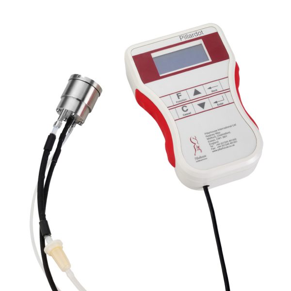
The Pillarhouse Drop-Jet head can be used to spray fluids at any angle in either upward or downward directions.
With its patented easy bleed and cleaning feature it is ideal for automation use. The head comes complete with a hand control unit which allows the operator to fully program the spray head.
The spray function and length of spray duration are both fully programmable at intervals in milliseconds. The controller can be triggered by 24V or RS232 interface.
The PillarDOT system can also be supplied as part of an X,Y axis unit with conveyor transfer.
Wide ranging use applications include solar cell, medical and electronic applications.
Optional Extras
An off-line process programming system
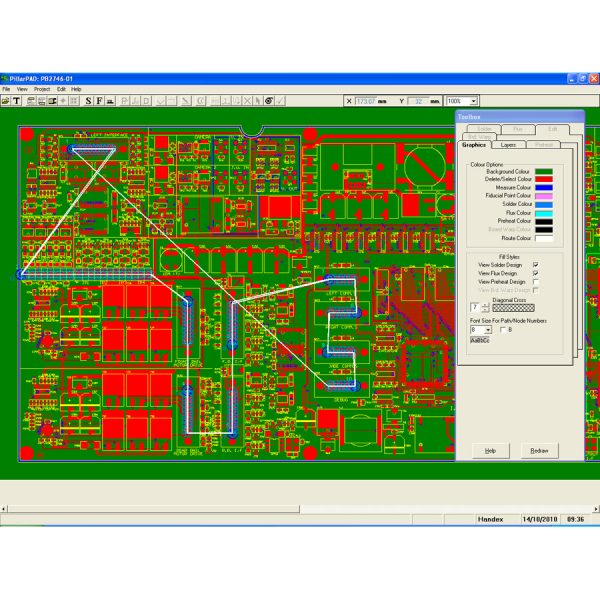
Product Description
PillarPAD is the Windows® based Off-line Programming system for the Pillarhouse International range of Selective Soldering Systems. It provides a user-friendly interface to allow the User to produce Process Programs away from the Production line. This results in reduced downtime for the production line when configuring for a new product.
PillarPAD is a two-part software package:
PillarPAD Import
PillarPAD Draw
The PillarPAD software package creates a single data file that can then be transferred to the required Selective Soldering System(s). One process program can be used on multiple Soldering Systems.
PillarPAD is available in two licensed formats
PillarPAD is compatible with XP®, Vista® , Windows7®, Windows8® and Windows10®.
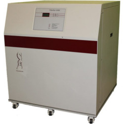
The PillarGEN Nitrogen generation system has been specifically designed to meet the Nitrogen supply requirements of the current range of Pillarhouse selective soldering systems.
The latest Nitrogen generation design technology combines compact size with ultra-quiet operation.
The PillarGEN-30 is specifically designed to integrate with the Pillarhouse Pilot bench top soldering system.
The PillarGEN-40 and -80 systems offer a fully integrated communication protocol to allow the monitoring and displaying of the unit’s status on the selective soldering machine. These values include oxygen concentration, flow rates and pressure – incoming air/outgoing Nitrogen.
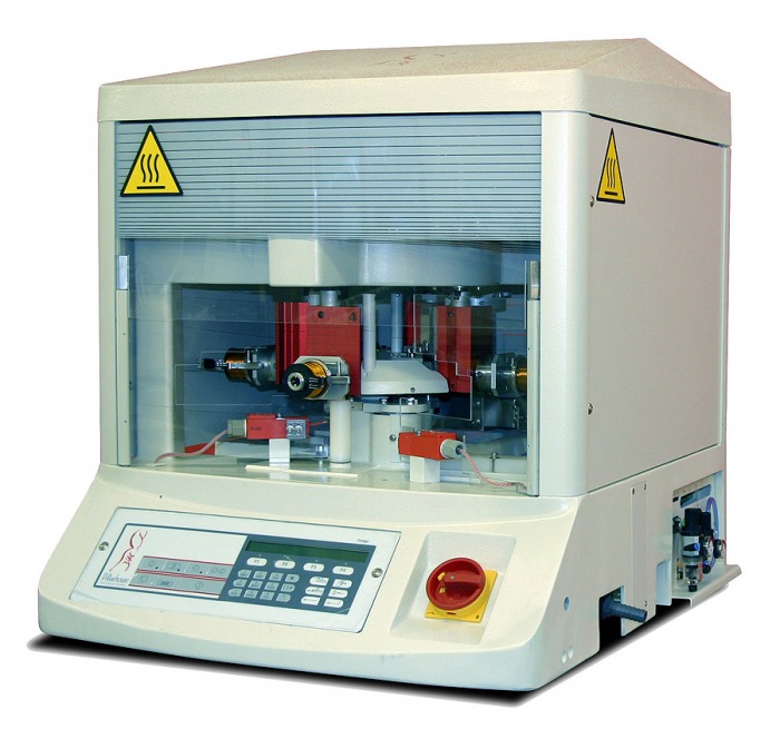
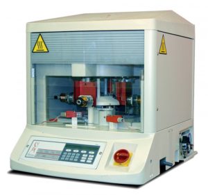
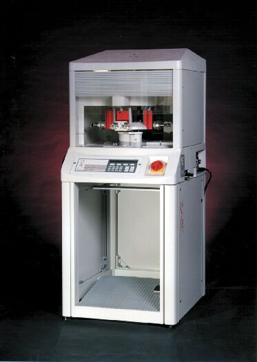
A versatile four station rotary bench top soldering machine ideally suited for high or low volume production, the Quadron, combines well proven pumped soldering techniques with advanced microprocessor technology. Much of its versatility is owed to the specially designed programming system which allows the user access to all fluxing and soldering parameters at any time, in addition, rapid product change-over is achieved quickly and easily through simple tooling design and program identification. The machine is at home both processing coils/sub-assemblies/transformers or small PCB’s in either small or large batches. Cycle times as low as 5 secs can be achieved.
Fluxing System
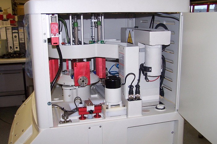
The flux is applied to the terminals via a crucible or sprung test probes, which is lifted from the bath to the component, this provides high quality and consistent repeatability. Flux application is of paramount importance, this is where the Quadron has an advantage, as it is able to control the application and avoid bobbin contamination by applying flux accurately. Excess flux and insulation residue is kept to a minimum by careful control of the dip height and immersion time, this being achieved through a microprocessor and stepper drive motors. The Quadron can be supplied with either a fixed flux bath or self-contained recycling flux tank which helps reduce the evaporation of the flux thinners.
Soldering
The Quadron uses a well proven solder pump system and incorporates a solder nozzle which can be of various designs to suit the product. Dross is removed from the nozzle prior to the next soldering operation
by increasing the pump speed and bursting solder from the nozzle, this occurs during the index operation and does not impede the overall cycle time. The component is dipped in the solder by means of the precision stepper driven tooling slide, which provides precise, accurate and repeatable results. Also, for the optimum soldered joint, Pillarhouse is able to provide a Nitrogen shroud which makes the soldering operation totally inert and helps prevent bridging, reduces dross and provides an improved quality. One major advantage the Quadron has is the ability to tilt a component out of the solder, this facility will help to prevent solder bridging of fine pitched connectors and the like.
Programming
The Quadron can be quickly and easily programmed to solder a wide range of different products, e.g. coils, transformers, wire terminations and small PCB’s. The machine has a memory capacity for 40 programmes (This can be increased to 160). The fluxing and soldering parameters are entered via a keyboard, to give full control of: solder bath temperature (to within ±1°C), flux and solder dip heights (increments of 0.1mm), and flux and solder immersion time (to within 0.1 of a second). Additional operations can also be controlled, e.g. component test facility, component unload and adjustment of the cycle time etc. A twenty-four hour wake-up timer is included as standard equipment which enables the machine to be automatically powered-on and bought up to temperature prior to the start of a working shift
Turnover
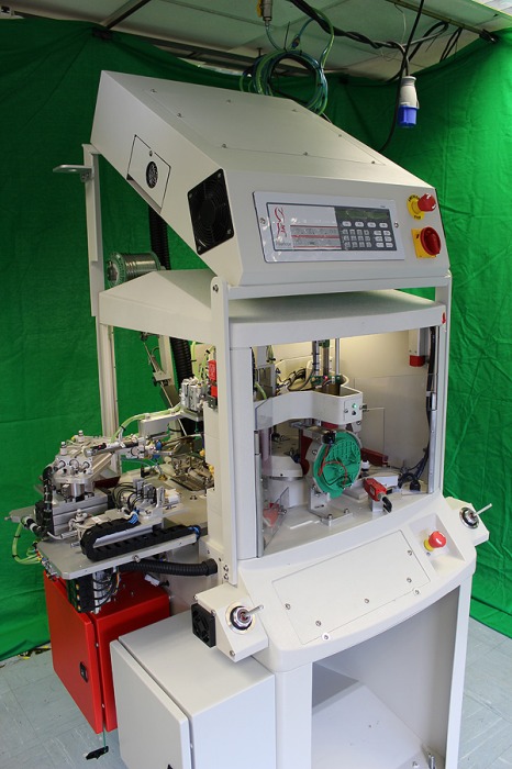
The optional turnover facility enables components with terminals on up to four sides to be handled on the same tooling, with fluxing and soldering performed at the same time without the need for the component to be re-loaded. Also, if a component has different soldering requirements on each side the Quadron can be programmed with different programming parameters for each side of the part.
Automatic Test/Unload
Optional continuity test and/or unload facilities offer the ability for components to be tested for electrical continuity or resistance prior to the component being automatically or manually ejected as a pass or fail.
Solder Top-up
This option ensures the solder level in the bath is kept constant; the level is automatically continually monitored using proximity switch system which instructs the system to automatically top-up the solder. This system uses a reel of 3mm diameter solder which is mounted on the rear of the machine; the solder is fed into the bath pneumatically.
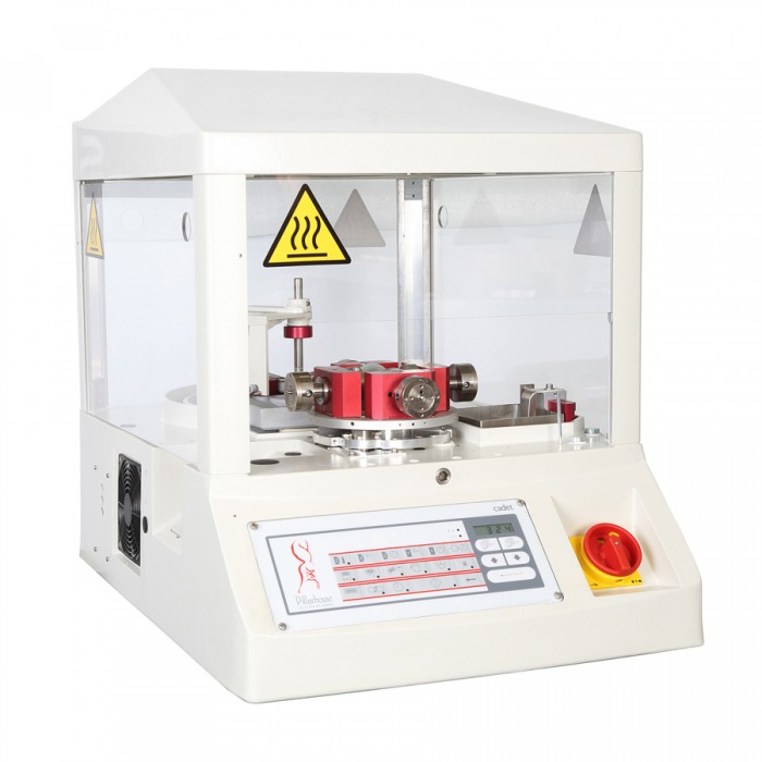
Uniwersalna obrotowa stacja lutownicza idealnie nadaje się do produkcji dużej lub małej objętości, Cadet, łączy w sobie dobrze sprawdzone techniki lutowania z zaawansowaną technologią mikroprocesorową. Znaczna część jego wszechstronności wynika ze specjalnie zaprojektowanego systemu programowania, który umożliwia użytkownikowi dostęp do wszystkich parametrów topnika i lutowania, a ponadto szybką zmianę produktu uzyskuje się szybko i łatwo dzięki prostemu projektowaniu narzędzi i identyfikacji programu.
Nanoszenie topnika
Przy użyciu tego samego systemu co w procesie lutowania strumień jest doprowadzany do końcówek za pomocą tygla, co zapewnia wysoką jakość i powtarzalność. Zastosowanie topnika ma ogromne znaczenie, to tutaj Cadet ma przewagę, ponieważ jest w stanie kontrolować aplikację i unikać zanieczyszczenia szpuli przez dokładne podawanie topnika. Nadmiar strumienia i resztki izolacji są ograniczone do minimum dzięki starannej kontroli wysokości zanurzenia i czasu zanurzenia, co osiąga się dzięki mikroprocesorowi i silnikom krokowym.
Lutowanie
Cadet wykorzystuje prosty, niezawodny system statyczny, który zapewnia czyste lutowie na stałym poziomie i objętości, oferując w ten sposób powtarzalne połączenia lutowane o wysokiej jakości w każdej operacji. Tygiel lub aplikator (który może być specyficzny dla produktu, jeśli jest wymagany) jest podnoszony ze stopionej kąpieli z lutu w celu zanurzenia końcówek komponentów w aplikatorze na dokładną głębokość i przez kontrolowany okres czasu. Wszelkie zanieczyszczenia lub kożuchy są usuwane bezpośrednio z powierzchni lutu przez unikalny podwójny system czyszczenia bezpośrednio przed lutowaniem. Temperatura lutowia jest kontrolowana przez procesor i oferuje użytkownikowi możliwość podgrzewania lutu do 500 ° C, co daje możliwość użycia zarówno lutów o wysokiej jak i niskiej temperaturze.
Programowanie
Cadet może być szybko i łatwo zaprogramowany do lutowania szerokiej gamy różnych produktów, np. Cewek, transformatorów, końcówek przewodów i małych płytek PCB. Urządzenie ma pamięć do 49 programów, a parametry topnika i lutowania są wprowadzane za pomocą klawiatury, aby zapewnić pełną kontrolę: temperatury kąpieli lutowniczej (z dokładnością do ± 5 ° C), wysokości strumienia topnika i lutowania (co 0,1 mm ), oraz czas zanurzenia strumienia i lutowania (do 0,1 sekundy). Dodatkowe operacje można również kontrolować, np. narzędzie do testowania komponentów, rozładowanie komponentów i regulacja czasu cyklu itp. 24-godzinny zegar budzika jest dostarczany jako standardowe wyposażenie, które umożliwia automatyczne włączanie i wyłączanie urządzenia, co umożliwia np. nagrzanie lutowia do określonej temperatury przed rozpoczęciem zmiany..
Opcje Systemu
The Cadet, bardzo wszechstronna maszyna może być jeszcze bardziej rozbudowana poprzez dodanie różnych opcjonalnych urządzeń, niektóre opcje są wymienione poniżej.
Obrotnica
Opcjonalny moduł obrotu umożliwia obsługiwanie komponentów z końcówkami po przeciwnych stronach przy użyciu tego samego oprzyrządowania, przy jednoczesnym topieniu i lutowaniu bez konieczności ponownego ładowania podzespołu. Ponadto, jeśli komponent ma różne wymagania dotyczące lutowania po każdej stronie, kadet zidentyfikuje różne parametry programowania.
Automatic Test/Unload
Opcjonalne urządzenia testujące i / lub wyładowujące umożliwiają przetestowanie komponentów pod kątem ciągłości elektrycznej lub odporności przed wyrzuceniem / rozładowaniem komponentu automatycznie lub ręcznie w funkcji przejścia lub usterki.
Kontroler gęstości topnika FDC
Ta opcja jest oddzielną samodzielną maszyną i znajduje się na podłodze sąsiadującej z częścią lutującą, kontroluje lepkość topnika i utrzymuje go przy właściwej grawitacji. FDC jest podłączony do maszyny do lutowania i nieustannie ponownie cyrkuluje topnik pomiędzy nim a zbiornikiem topnika w maszynie. Po powrocie do FDC topnika, przechodzi przez Hydrometr, który monitoruje jego lepkość, jeśli staje się zbyt gęsty, dodaje się rozcieńczalniki, aż do uzyskania odpowiedniej konsystencji.
Specyfikacja
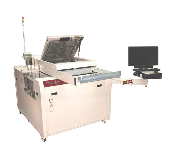
Designed to meet the needs of the small batch manufacturer who requires high levels of production flexibility. The Jade Prodex offers the ability to regularly change solder alloys without incurring expensive down time, whilst the solder bath cools down and heats up during a regular manual changeover process.
The Prodex is an offline system, incorporating a quick load twin PCB universally adjustable rotary table transport system to allow simultaneous load / unload during product processing.
In its basic format, the Prodex is configured with a single solder bath. In its Duplex guise, the machine can be configured with twin adjacent solder baths on independent Z axis drives. This achieves increased production flexibility by permitting use of two different nozzle tip sizes which can be allocated as process requirements dictate within any particular area on a PCB.
All Prodex configurations can be offered with optional automatic heated solder bath change stations. Using this system the non-operational solder bath and pump system can be stationed at one of the two optional heated park positions located at either side of the main machine. This heated station, maintains the correct solder temperature within the bath that is idle so that when changeover occurs, the replacement bath can resume immediate production. A single automatic solder bath change station is identified as a PLUS configuration, whilst twin stations (located at both sides of the machine) are identified as PLUS PLUS configurations. On this basis Duplex machines with the PLUS PLUS identity will operate with 4 individual solder bath and pump systems.
The Prodex series is controlled by a PC, through PillarCOMM, a Windows® based ‘Point & Click’ interface with a PCB image display.
Additionally our optional PillarPAD offline programming package allows the operator to produce programs independently from the machine using Gerber data.